Bronco Forum - Full Size Ford Bronco Forum banner

Steering box reinforcment bracket.

24K views 62 replies 25 participants last post by  Shadofax  
#1 ·
Has anyone ever built a steering box reinforcement bracket that ties the steering box to either the crosmember or the pass side frame rail or both?

My whole drivers side frame horn twists when turning now from the added leverage of the dropped pitman arm.

They make such a brace for Jeeps, but nothing for us. So I am thinking of having one fabricated.

Anyone ever try it?
 
#4 ·
is the box moving or the frame rail???

if the frame rail is moving then i would just build a crossmember behind the bumper to tie the two together...its actually a good idea especially if u ever hit something head on u might not twist the rails...

im gonna be doing an xmember... really its just a winch mount but u get the idea
 
#5 ·
is the box moving or the frame rail???
Both, the box is twisting the frame rail.


if the frame rail is moving then i would just build a crossmember behind the bumper to tie the two together
I plan on doing this as well, but the box is puting tremendiouse strain on the frame. It has already cracked it once. I need to actualy brace the neck on the output shaft of the box to another structural point in order to relive the stress on the drivers side frame rail.
 
#15 ·
but I have never heard this happen to a ford.
Several guys have had it happen and had cracks on here.

I havn't tried it because I have never seen a ford frame twist like that. Your frame is boxed there, right?
Yes it's boxed.

A freind of mine had the frame brake slap in 2 at the steering box on her 93 F-150.

do what gkr did, and an x member and then a brace, i'll be doing the same when i replace some stuff under the front end
I'm gonna try. I dont have any fab ability.


Something like this?
Image

Image

Image
Thats what I'm talkin about :thumbup
 
#21 ·
Sorry to drag up an old post like this but I was wondering how Gack got on with his plans and how GKR's is holding up 15 moths down the track?

I've snapped 3 bolts in three weeks, one three weeks ago and two two days ago. Two of the bolts were an easy removal, but the final one requires the box out and some serious work done as the bolt is a couple of threads inside the steering box. The frame has craked in the past but has been repaired with no sign of recracking in the old or new positions. Standard height, 31x10.5/15 tyres. Not interested in this becoming a recurring issue. Done a lenghty search and will be looking at the rivet tomorrow, and look for anything else out of place, or missing.

Josh
 
#24 · (Edited)
Started mocking the thing up...after only what, 6yrs?

Nothing is welded yet, just mocking up and getting ideas.

Image


Image


Image


Image


Image


Comments?

Criticisms?

Ideas?
 
#25 ·
how are you going to attach it to the crossmember.

I have had mine crack and the left frame horn detach from the crossmember, mine was awful
 
#28 ·
I have had mine crack and the left frame horn detach from the crossmember, mine was awful
This thread tells the story of my frame crack, the entire thing is a result of the forward lower driver side crossmember rivet being loose.
http://fullsizebronco.com/forum/showthread.php?t=91282

As time goes on, we are going to see more and more of this happening.

how are you going to attach it to the crossmember.
3/8" angle bolted on with the two bolts you see facing you for the pass side (Drivers side beam) drop bracket, with a gusset welded in it between the bolts. The plate that is clamped to the box is also 3/8", the tube is just something my neighbor had laying around. I'm not sure what it is, probably "Poop Pipe" but it should work for this. (This not a roll cage, or rock slider)

This should be far stringer than my original "Lawn Chair Led" idea I borrowed from the Jeep guys.
http://fullsizebronco.com/forum/showthread.php?t=94108

I think GKR had the right idea.
Ok, well where do you see the deficiency in this design at?
Give me some suggestions. :thumbup

I had a simmilar issiue with mine, I never cracked the frame there tho. I welded part of the engine x-member right to the frame, and put a brace in from side to side just undernieth my rad. support.
I did the same with the crosmember, but wile doing my annual "Check the frame at the steering box for twist" I realized those welds had finally pulled free. The weld holding the crack in the frame is still good, but the bottom of the frame twists away from the crosmember when turning right.

I have also thought of putting a brace in front of the box connecting both frame horns, but after watching it flex, I'm not sure it would o much.
I even thought about using this for just that purpose, but decided against it.
http://fullsizebronco.com/forum/showthread.php?t=181543
 
#26 ·
I had a simmilar issiue with mine, I never cracked the frame there tho. I welded part of the engine x-member right to the frame, and put a brace in from side to side just undernieth my rad. support. No flex or anything, and with that and a new gear box, I don't have that typical loose sterring wheel play that these trucks always have. Only spot I broke the frame was right behing the passanger side spring bucket.
 
#27 ·
I think GKR had the right idea.
 
#29 ·
i don't think that tying the box into the frame by way of the TTB crossmemberon is a good idea. you want to add stiffness and strength to the frame, tie the frame horns together. i'm not saying the box couldn't handle it, but i think you're going from A to B, to D, to get to C.

the crossmember that has the axle beams bolted to it has enough stress on it with the TTB drop brackets, this would only add more work for it, and i wouldn't take that chance.

that pipe doesn't look beefy enough. i know you don't do things half-ass, nor underbuild them, but that pipe just doesn't look like it would be up to the job. remember, this isn't just holding the LF frame horn from moving, there is going to be more stress because it already does move, and because that side is weakened to begin with. Nor do i see any real triangulation.

i am not a fabricator Gack, don't claim to be. but that doesn't look like it would be enough. At the very least, if you want to tie the horns together to add strength, then do that, i wouldn't use the box and the TTB crossmember as the go between. Go right to the source.
 
#32 ·
i don't think that tying the box into the frame by way of the TTB crossmemberon is a good idea. you want to add stiffness and strength to the frame, tie the frame horns together.
I want the brace to stop the steering box from pushing the frame away from the crosmember when turning right.

This truck had the same problem.


I told them several times that the problem was the lower rivet was loose, they refused to listen claiming the frame was just weak and needed to be tied together. So they welded a 2" tube from frame horn to frame horn and then plated the frame where the crack was. I asked them to ditch the "Xtreme" drop pitman arm and build a brace for the box that connected the snout to the crossmember, they ignored me.

Just a year or two later and it looked like this.


the crossmember that has the axle beams bolted to it has enough stress on it with the TTB drop brackets, this would only add more work for it, and i wouldn't take that chance.
It already had the job of holding the frame together, I am simply adding another connection.

that pipe doesn't look beefy enough.
What would be sufficiant?
I think it is 1.5" with a 3/16" wall, but I'm not sure. I'll measure it next time I work on it.

Remember, the only stress on it will be tension.....That's it. It's not going to see any other force, the frame takes care of all of that. It's sole purpose is the keep the snout of the steering box from moving away from the cross member to the left hand side during a right turn. There will be no rotational forces on it.


that pipe just doesn't look like it would be up to the job. remember, this isn't just holding the LF frame horn from moving, there is going to be more stress because it already does move
I plan on welding the frame back to the crossmember, this is to prevent it from happening again. (Hopefully)

Nor do i see any real triangulation.
This is where I think folks are confused about how the box moves and where the forces are at. This will "Create" a triangle where one does not exist now between the steering box/frame and the crossmember. And, all the force on the brace, with the exception of the U-bolt, will be in tension.


Then again, I could be completely wrong and be building a candidate for the scary steering page. If so, I promise to paint it a nice neon color so it stands out good.:toothless


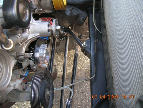
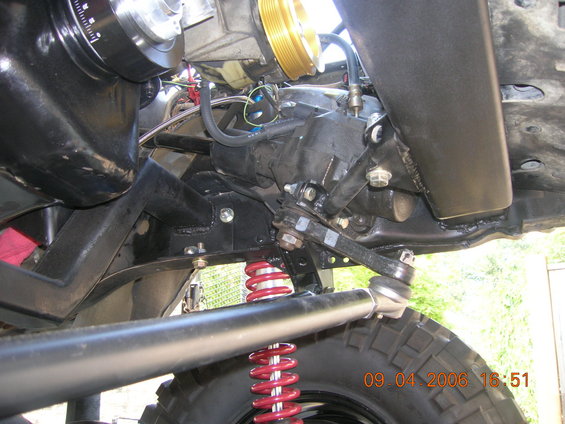
This shot isn´t quite good, but I think´ll do. It´s a bent tube, welded to a metallic angle one of it´s and ends bolted to the engine crossmember, the other one (as you are planning to) goes to the exit of the gearbox


Hope that helps :thumbup
Does it work?
 
#33 ·
It could be contributing. Stick your head under the bumper and watch the steering box as you have someone turn the wheel 1/2 turn from left to right.

Does the box push the bottom of the frame away from the crossmember?
 
#34 ·
A friend running the same height lift had the same issue-- both rivets got loose, causing the frame to collapse, causing pretty much no steering on the trail. When we did his SAS, I built a bracket out of 1/4" x 6 channel, with a plate mounted at about 45*. The angled plate bolts to the inside and front of the crossmember, the other end bolts through the bottom of the frame. That along with new bolts in place of the crossmember rivets seems pretty darn solid.

Yours seems like a really good start, but I would look into some triangulation of the plate at the steering box, seems like it may want to fold. Of course this shouldn't really see any load at all if the crossmember is properly attached.