This should cover most 87-96 V8s (302\351); for the I6s (300)s the solenoids are in the same general area, as well as the valves. You can use this article as a basis to replace yours, just keep in mind it will be slightly different.
Parts you'll need:
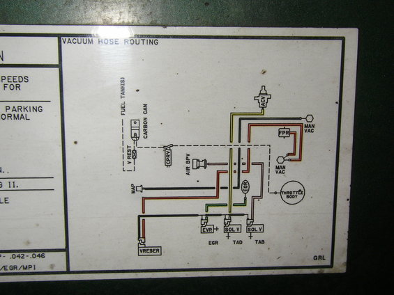
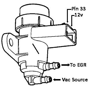
To get started, I'll explain what the point of it all is. The EEC (Electronic Engine Control or computer) uses electronic solenoids to send vacuum to valves (in this case, three valves: the EGR, the TAB (next to the SMOG pump), and the TAD (behind the upper intake plenum). The EEC sends a signal to the solenoid and it "opens" the valve to allow the engine vacuum through. The easiest way to understand this is with the EGR.
At idle, the EGR is normally closed; but when you get to highway speeds, the EEC wants the EGR to open. The EEC sends the signal to "open" the valve to let the vacuum through and the vacuum opens the EGR. For a more in depth description of the TAB\TAD systems,
see this post (Thanks WuTang).
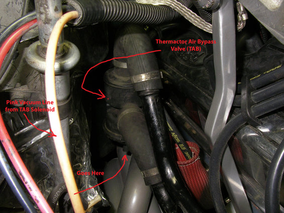
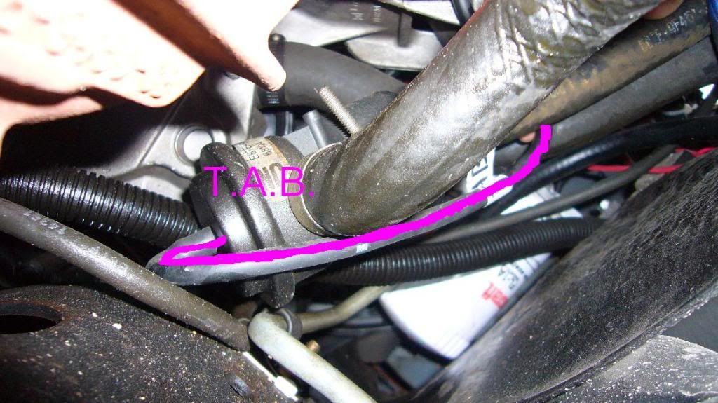
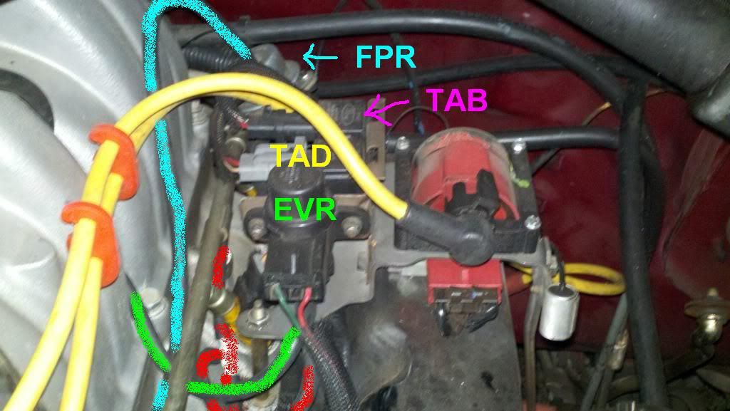
The TAB valve works the same way, it either directs the air pumped from the smog pump onward to the TAD valve (we'll get there) or out to nowhere (not used). When the TAB valve directs the air onto the TAD valve, the TAD valve either directs the air from the smog pump down into the catalytic converter, or into the back of the engine. Here's a pic:
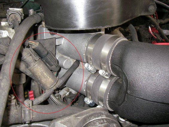
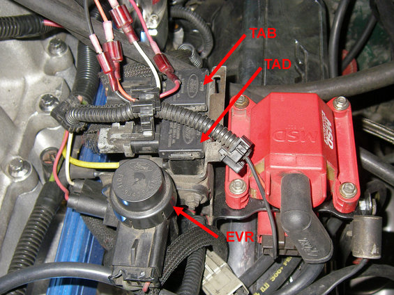
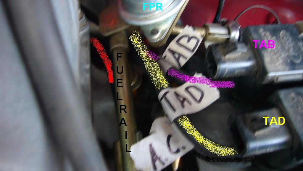
You can see the coil, the TAD, TAB, and EVR solenoids (EVR controls the EGR). You can see
the yellow line coming from the TAD solenoid, the pink line coming from the TAB solenoid, and the line coming from the EVR is green; can't see it, but it's there. What you can't see (but when you look at your truck you can) are the vacuum hoses that plug into the bottom of the solenoids. This is where the vacuum is supplied to the solenoids. On the EVR(EGR) solenoid, it goes straight to the vacuum tree (vacuum hook-up on the intake manifold). On the EVR(EGR), the top (green) hose goes straight to the EGR valve, and the Bottom (red) hose goes straight to the intake manifold.
The TAB\TAD valves are a little different, but not much. The only difference is that the red line
(yes, the exact same one that goes to the bottom of the EVR\EGR solenoid) goes all the way over to the vacuum canister on the fender, the vacuum canister stores vacuum for these valves (TAB, TAD). Then there is a black vacuum line coming out of the vacuum canister next to the red line that goes all the way back over to the bottom ports of the TAD\TAB solenoids.
From the top of the TAB solenoid a pink hose is run to the valve right next to the smog pump
(I'll show a pic after this rambling paragraph). From the TAD, there's a yellow hose run to
the TAD valve behind the intake manifold.
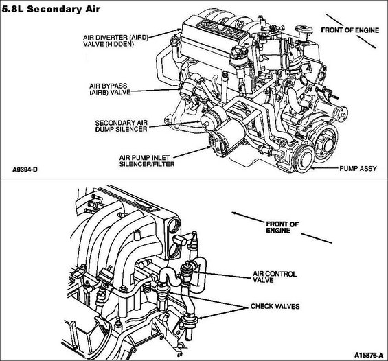
Here's a pic of a motor that's pulled, just so you can see where the valves are and such;
but you don't have to pull the motor, lord knows I didn't.
![Image]()
You can see the yellow line going to the "diverter" valve (TAD). You can also see
the “bypass” valve (TAB) (you can't see the vacuum line going there, but when you
look at it on your truck you'll see it), plus the EGR and all that other stuff.
Ok, so now that we have an idea of what goes on, let's get started. To avoid confusion,
only run one hose at a time. We need to replace\rerun the red vacuum line, so take a
piece of vacuum hose and run it from the vacuum tree on the intake manifold to
the vacuum canister.
Run it around the back of the engine (I ran it on top of the passenger side valve cover,
under the upper intake plenum). Plug the hose into the vacuum canister where the red
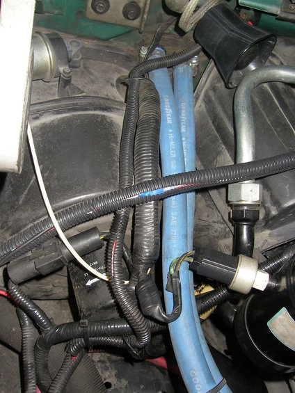
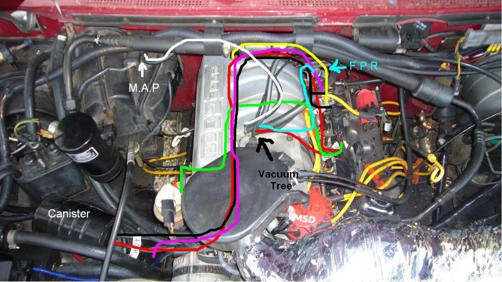
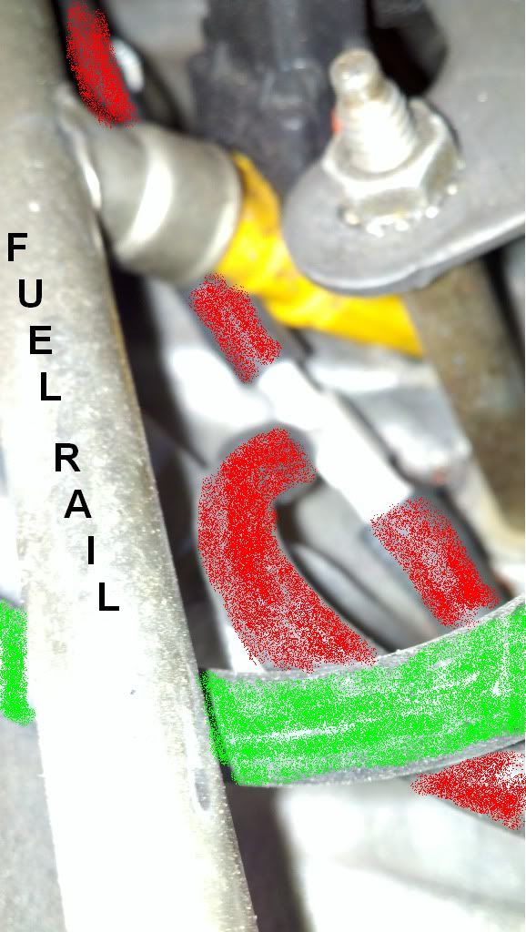
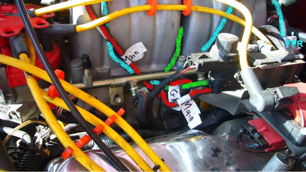
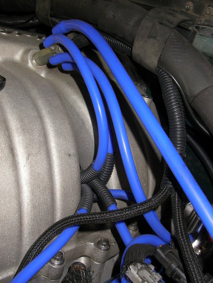
hose plugged into. Here's an overhead pic of how I have my vacuum lines run, you can
also use this to see how to run new (rubber) lines to the FPR (Fuel Pressure Regulator)
and the MAP (Manifold Absolute Pressure) Sensor. In all my pics I tried to use the most
sophisticated graphic design program known to man (Paint) to help. I tried to keep the
coloring the same as the original colors, with the exception of the MAP sensor and FPR:
![Image]()
Go back to the driver side of the intake, where the solenoids are, and cut the vacuum line
you just ran so you can put a "T" on it and run a very short vacuum line to the bottom of
the EVR\EGR solenoid:
![Image]()
From the T you connect a short vacuum hose to the bottom of the EVR solenoid, Pic:
![Image]()
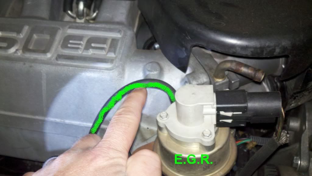
Then run a vacuum hose from the top of the EVR solenoid where the green line used to be
(see pic above) to your EGR valve. I ran the hose through the hole in the middle of the
intake plenum, and then ran it up to the EGR:
![Image]()
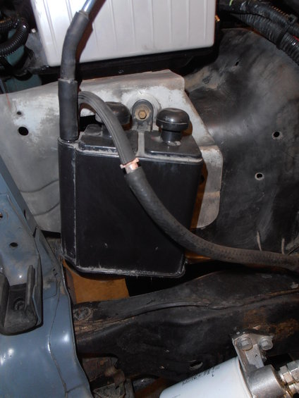
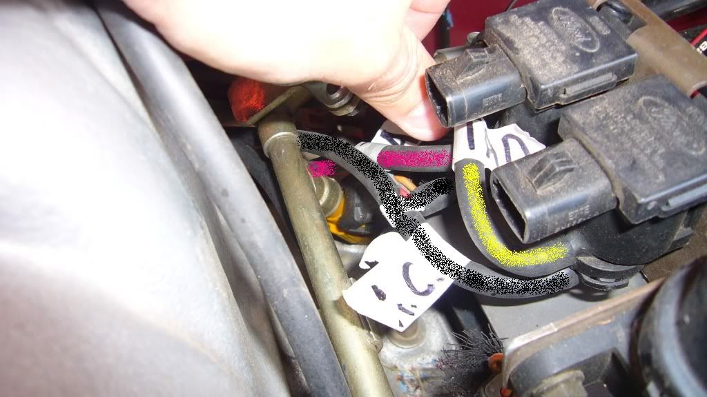
Now go back to the vacuum canister, and run a vacuum hose from the OTHER plug on the
canister(formerly black line) to the bottom port on the 2 solenoids for TAB\TAD. You will
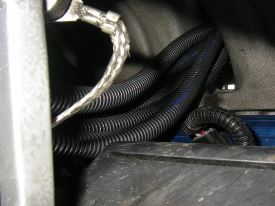
need another "T" so that you can split the hose into 2 hoses, one for each solenoid.
Kind of hard to see in this pic, you can see the white tip of the T, but it'll make sense
when your doing it:
![Image]()
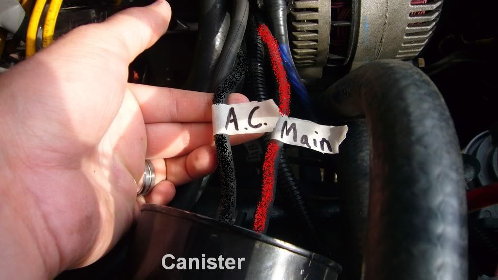
2 hoses coming from the vacuum canister (A.C. stands for After Canister):
![Image]()
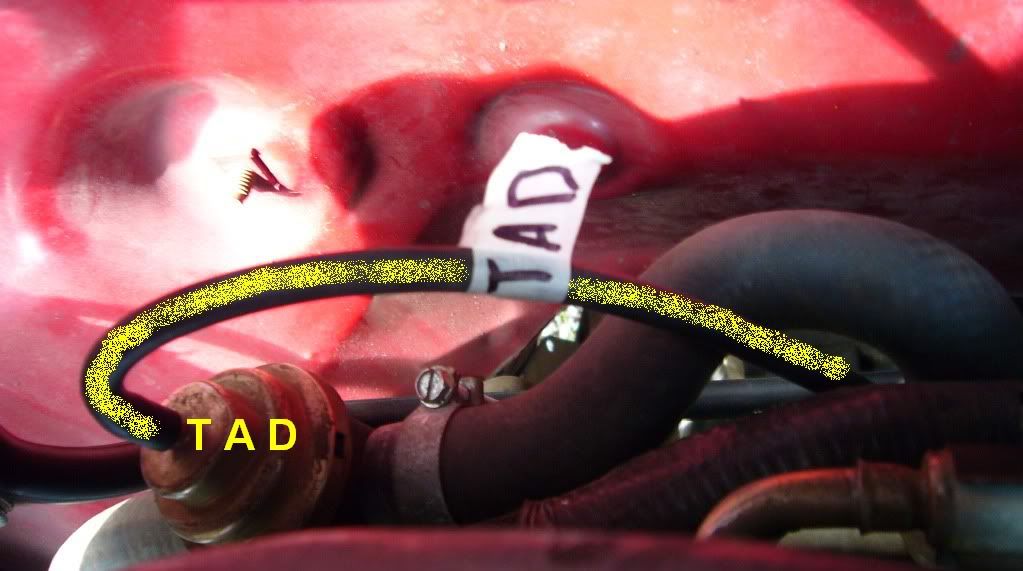
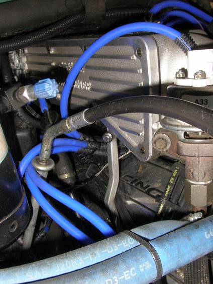
After that, run a hose from the top port on the TAD (front of the 2 solenoids) to the diverter
valve behind the intake plenum (originally it was a yellow hose). Here's a pic, I literally
set my camera on the intake plenum, and took a picture behind it; so it's kind of close up:
![Image]()
Almost done!
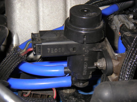
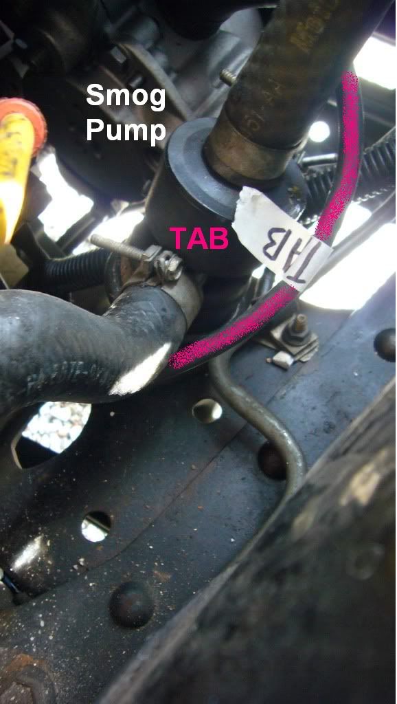
All that's left is to run a vacuum hose from the top port of the rear-most solenoid (TAB)
to the valve that’s right by the smog pump. This was the hardest part for me, but I have
fat fingers, and truthfully it wasn't that bad; just annoying. Here's a pic, it might be easier
to plug the hose in from under the truck, but I was able to do it from the top.
![Image]()
![Image]()
Here's the solenoids with the TAD, TAB, and the A.C. (After Canister) line:
![Image]()
That’s it for the SMOG stuff, but if you want to completely do away with all the plastic crap,
you can run a new hose from the vacuum tree straight to the FPR (fuel pressure regulator),
as well as a vacuum hose straight from the vacuum tree to the MAP sensor.
Here's some pics of the whole set up, you can see the hoses going to the solenoids:
![Image]()
If you change out the FPR and the MAP hoses, then you can literally take out the plastic
crap so it doesn't clutter up your engine bay, like I did:
That's pretty much it, now you have a rubber vacuum system!
Thanks goes to WuTang for proofreading\ideas, and thanks to Miesk5 for clarification on what
years this applies to and his never-ending knowledge!
Parts you'll need:
- All available from a local autoparts store (except one)
- Approximately 20' of vacuum hose (5\32")
- 2 Vacuum T's
- Patience
To get started, I'll explain what the point of it all is. The EEC (Electronic Engine Control or computer) uses electronic solenoids to send vacuum to valves (in this case, three valves: the EGR, the TAB (next to the SMOG pump), and the TAD (behind the upper intake plenum). The EEC sends a signal to the solenoid and it "opens" the valve to allow the engine vacuum through. The easiest way to understand this is with the EGR.
At idle, the EGR is normally closed; but when you get to highway speeds, the EEC wants the EGR to open. The EEC sends the signal to "open" the valve to let the vacuum through and the vacuum opens the EGR. For a more in depth description of the TAB\TAD systems,
see this post (Thanks WuTang).
The TAB valve works the same way, it either directs the air pumped from the smog pump onward to the TAD valve (we'll get there) or out to nowhere (not used). When the TAB valve directs the air onto the TAD valve, the TAD valve either directs the air from the smog pump down into the catalytic converter, or into the back of the engine. Here's a pic:
You can see the coil, the TAD, TAB, and EVR solenoids (EVR controls the EGR). You can see
the yellow line coming from the TAD solenoid, the pink line coming from the TAB solenoid, and the line coming from the EVR is green; can't see it, but it's there. What you can't see (but when you look at your truck you can) are the vacuum hoses that plug into the bottom of the solenoids. This is where the vacuum is supplied to the solenoids. On the EVR(EGR) solenoid, it goes straight to the vacuum tree (vacuum hook-up on the intake manifold). On the EVR(EGR), the top (green) hose goes straight to the EGR valve, and the Bottom (red) hose goes straight to the intake manifold.
The TAB\TAD valves are a little different, but not much. The only difference is that the red line
(yes, the exact same one that goes to the bottom of the EVR\EGR solenoid) goes all the way over to the vacuum canister on the fender, the vacuum canister stores vacuum for these valves (TAB, TAD). Then there is a black vacuum line coming out of the vacuum canister next to the red line that goes all the way back over to the bottom ports of the TAD\TAB solenoids.
From the top of the TAB solenoid a pink hose is run to the valve right next to the smog pump
(I'll show a pic after this rambling paragraph). From the TAD, there's a yellow hose run to
the TAD valve behind the intake manifold.
Here's a pic of a motor that's pulled, just so you can see where the valves are and such;
but you don't have to pull the motor, lord knows I didn't.
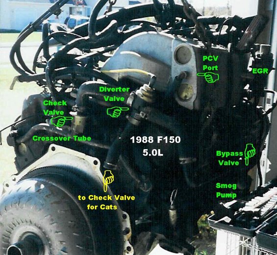
You can see the yellow line going to the "diverter" valve (TAD). You can also see
the “bypass” valve (TAB) (you can't see the vacuum line going there, but when you
look at it on your truck you'll see it), plus the EGR and all that other stuff.
Ok, so now that we have an idea of what goes on, let's get started. To avoid confusion,
only run one hose at a time. We need to replace\rerun the red vacuum line, so take a
piece of vacuum hose and run it from the vacuum tree on the intake manifold to
the vacuum canister.
Run it around the back of the engine (I ran it on top of the passenger side valve cover,
under the upper intake plenum). Plug the hose into the vacuum canister where the red
hose plugged into. Here's an overhead pic of how I have my vacuum lines run, you can
also use this to see how to run new (rubber) lines to the FPR (Fuel Pressure Regulator)
and the MAP (Manifold Absolute Pressure) Sensor. In all my pics I tried to use the most
sophisticated graphic design program known to man (Paint) to help. I tried to keep the
coloring the same as the original colors, with the exception of the MAP sensor and FPR:
Go back to the driver side of the intake, where the solenoids are, and cut the vacuum line
you just ran so you can put a "T" on it and run a very short vacuum line to the bottom of
the EVR\EGR solenoid:
From the T you connect a short vacuum hose to the bottom of the EVR solenoid, Pic:
Then run a vacuum hose from the top of the EVR solenoid where the green line used to be
(see pic above) to your EGR valve. I ran the hose through the hole in the middle of the
intake plenum, and then ran it up to the EGR:
Now go back to the vacuum canister, and run a vacuum hose from the OTHER plug on the
canister(formerly black line) to the bottom port on the 2 solenoids for TAB\TAD. You will
need another "T" so that you can split the hose into 2 hoses, one for each solenoid.
Kind of hard to see in this pic, you can see the white tip of the T, but it'll make sense
when your doing it:
2 hoses coming from the vacuum canister (A.C. stands for After Canister):
After that, run a hose from the top port on the TAD (front of the 2 solenoids) to the diverter
valve behind the intake plenum (originally it was a yellow hose). Here's a pic, I literally
set my camera on the intake plenum, and took a picture behind it; so it's kind of close up:
Almost done!
All that's left is to run a vacuum hose from the top port of the rear-most solenoid (TAB)
to the valve that’s right by the smog pump. This was the hardest part for me, but I have
fat fingers, and truthfully it wasn't that bad; just annoying. Here's a pic, it might be easier
to plug the hose in from under the truck, but I was able to do it from the top.
Here's the solenoids with the TAD, TAB, and the A.C. (After Canister) line:
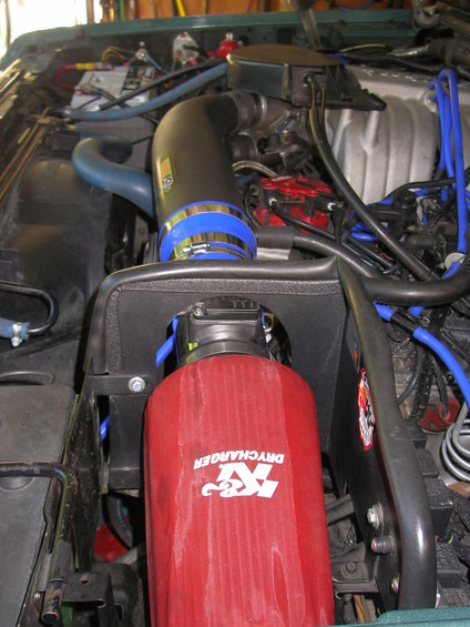
That’s it for the SMOG stuff, but if you want to completely do away with all the plastic crap,
you can run a new hose from the vacuum tree straight to the FPR (fuel pressure regulator),
as well as a vacuum hose straight from the vacuum tree to the MAP sensor.
Here's some pics of the whole set up, you can see the hoses going to the solenoids:
If you change out the FPR and the MAP hoses, then you can literally take out the plastic
crap so it doesn't clutter up your engine bay, like I did:
That's pretty much it, now you have a rubber vacuum system!
Thanks goes to WuTang for proofreading\ideas, and thanks to Miesk5 for clarification on what
years this applies to and his never-ending knowledge!


.jpg)