Bronco Forum - Full Size Ford Bronco Forum banner

Overhead Console Display Fix

38K views 48 replies 21 participants last post by  ATX-BBQ  
#1 · (Edited by Moderator)
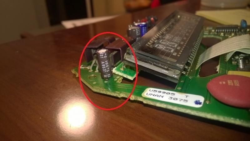
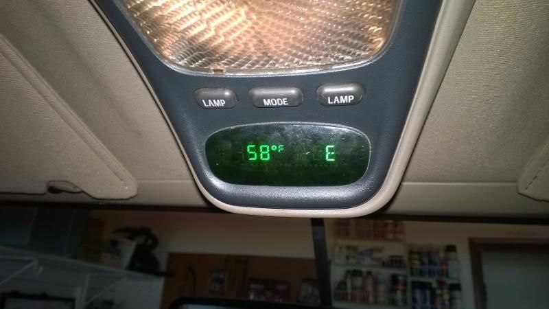
Got a blank overhead console temperature/compass display? Here's how to fix one variant of the circuitry that is at fault. This is on a '95 model; there are two different circuit boards commonly installed in the overhead console. Both tend to fail after so many years. The somewhat more common circuit board has a "510" resistor that burns out, and replacement of the resistor is documented in a different thread on the forum. This thread shows repair of the other less common circuit board, which has a capacitor that leaks and causes the display to boot up after a long delay or not at all. If you get halfway through this guide and your circuit board does not match the pictures, search the forums for info on replacement of the 510 resistor.

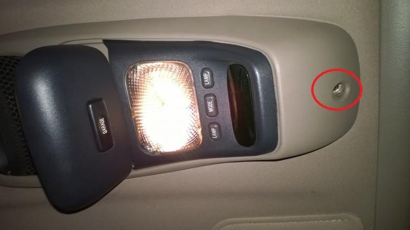
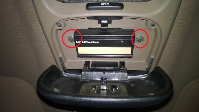
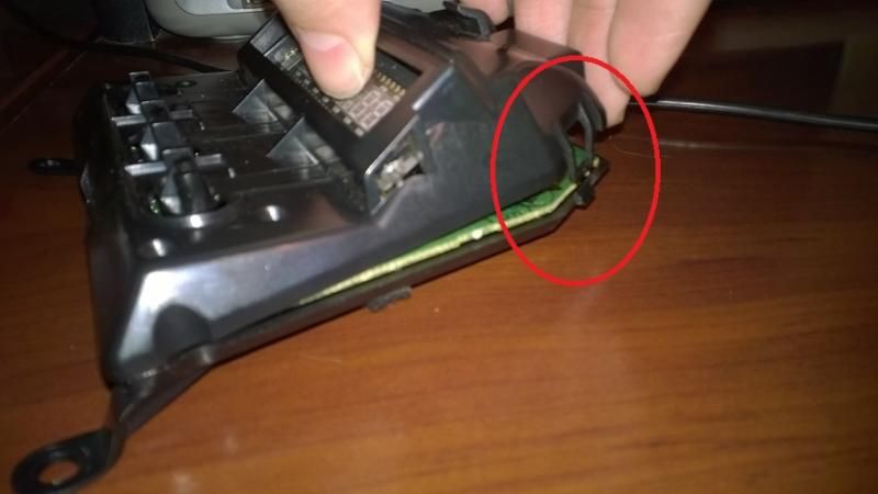
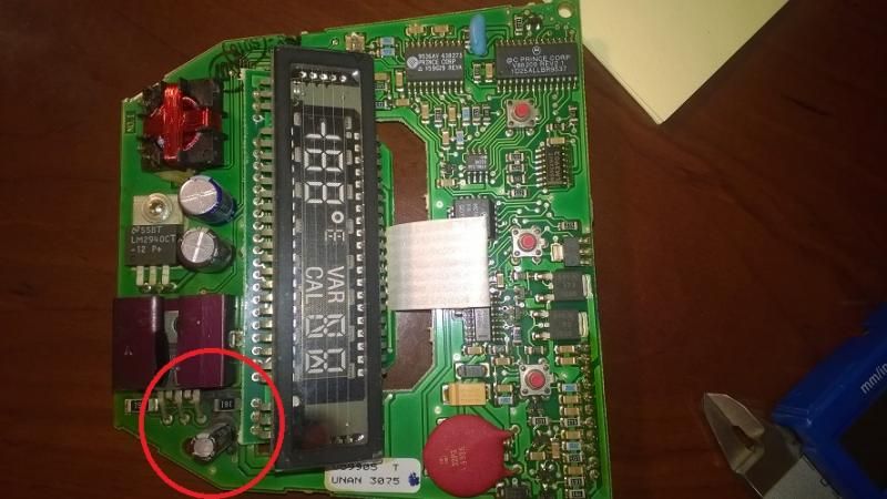
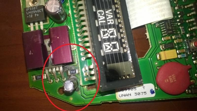
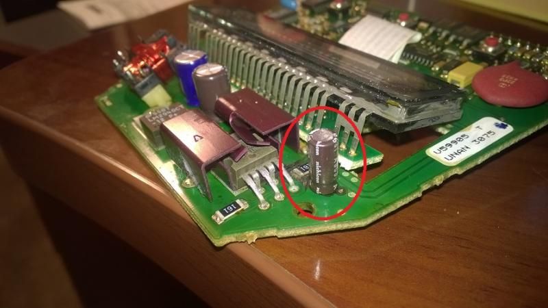
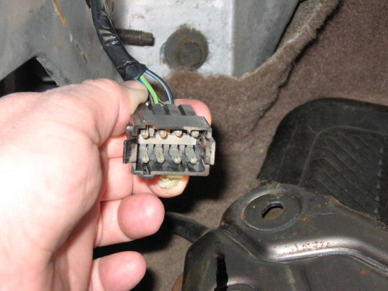
Start by removing the overhead console from the vehicle. There are three screws that you will need to remove before it will drop down. See pictures for screw locations circled in red.
Image

Image
 
  • Like
Reactions: AmericanSavage
#2 · (Edited by Moderator)
Once the console drops down, unplug the black electrical connector tethering it to the vehicle. There is a small black tab on the connector that you press down and the connector pulls apart.

Now remove the console electronics module from the console assembly. Remove the screws circled in red.
Image


Work the electronic module out. Be gentle. You'll need to disconnect its electrical connector, just wiggle and pull.
Image


You should have the module free now.
Image


You'll notice it has two clips at the front and a hooked tab at the rear. Gently bend open the front clips and lift up the front, and slide the cover apart to remove the circuit board. Remove any static electricity from your body before touching the circuit board. When handling the circuit board, hold it by its outside edges.
Image

Image

Image
 
  • Like
Reactions: AmericanSavage
#38 ·
Once the console drops down, unplug the black electrical connector tethering it to the vehicle. There is a small black tab on the connector that you press down and the connector pulls apart.

Now remove the console electronics module from the console assembly. Remove the screws circled in red.
Image


Work the electronic module out. Be gentle. You'll need to disconnect its electrical connector, just wiggle and pull.
Image


You should have the module free now.
Image


You'll notice it has two clips at the front and a hooked tab at the rear. Gently bend open the front clips and lift up the front, and slide the cover apart to remove the circuit board. Remove any static electricity from your body before touching the circuit board. When handling the circuit board, hold it by its outside edges.
Image

Image

Image
What happens if you reverse the polarity on the 510 Resistor. I sent mine out for repair. When I got it back and plugged it in the display lit up, went out, and smoke came from the board.
 
#3 · (Edited by Moderator)
Examine the circuit board. If you have the particular variant that has a failure-prone capacitor, it will look like this one. You're looking for the capacitor circled in red, and what looks like an oil spill at the base of it.
Image


If this matches your board, notice the black stuff around the base of the capacitor. This is where the capacitor has leaked out its electrolytic solution. The capacitor ceases to function correctly or may not function at all. In some cases the leakage can actually damage the printed circuit and nearby components. For this reason, replacing the capacitor may not fix your display if the circuits are badly damaged. The circuit board pictured is not too bad; the capacitor still functioned a little bit, so after about 10 minutes of driving around the display would light up and work. Shut off the truck, and you had to wait for the delay again.

More pictures below of my board. If yours is badly damaged, such as the printed circuit being split or lifted off the board, you may want to find a replacement that is in better condition. The board that came on my Bronco was too badly damaged to work with a capacitor replacement, so I installed a junkyard board from a 1996 Explorer that was in better shape. This is the board that is pictured, and the capacitor replacement was successful.
Image

Image


If you do need to replace your board or want a spare, check Broncos and also 1991-1997 Explorers. In either 1998 or 1999 the design changed, and you can usually tell by the different connectors and sometimes white plastic.
 
  • Like
Reactions: AmericanSavage
#4 · (Edited by Moderator)
Here's where you're going to need to have your supplies ready to fix this. You'll need a soldering iron: pictured is the 20w/40w Radio Shack model I used, which works great for smaller projects. It cost about $25. I don't recommend using a soldering gun with high wattage, as you can damage the circuit board and nearby components. Honestly, 20 watts should be sufficient.

Image


You'll need some solder. This is the kind I use, also available at Radio Shack, and it works awesome. Pictured next to the bad capacitor that is to blame for all this.
Image


If you flip the circuit board over you'll see the base of the capacitor's pins. This is where you'll apply heat, melting the solder and pulling out the old capacitor for replacement of the new one.
 
  • Like
Reactions: AmericanSavage
#5 · (Edited by Moderator)
Now the important bit, the new capacitor. It's got to be the right one for the job, not all capacitors are the same! Instead of throwing specs at you (that are printed on the capacitor body) I will suggest a specific part number.

The stock capacitor is usually a Nichicon brand A9531. It has since been discontinued. Good riddance, it clearly wasn't that great. However, I'm told Nichicon is a good manufacturer and so my replacement was another Nichicon and ordered it through Digi-Key, which is a great seller. Their site is a little tricky so just put in the part numbers and go that way.

Digi-Key part number: 493-11653-1-ND
Manufacturer part number: UPV0J121MFD1TD
This is one of Nichicon's long-life models, made for way more cycles than the standard line capacitors, and the size is almost identical to the original capacitor (a hair taller but fits fine). Overall it should be a much longer life unit.

My cost at the time was about 54 cents per capacitor, so why not splurge and get two? Just in case you lose one or something.

Image


The capacitors come packaged like this, just pull one off and trim the leads down short so it won't be sitting up high.
Image
 
  • Like
Reactions: AmericanSavage
#6 · (Edited by Moderator)
Before you remove the old capacitor and install the new one, note the polarity. All you have to do is make sure the white stripe on the new capacitor is in the same position as the old one was. THIS IS IMPORTANT!
Image


You're simply going to melt the solder from the leads on the old capacitor (from the underside of the circuit board) and pull the old capacitor up and out while the solder is liquid. The new capacitor installs the same way, remember the polarity. You want the new capacitor to sit down on the board and not be sticking way up, which would cause the plastic module cover not to fit right. Keep heating up both leads and work the new capacitor down in. Take your time. Make sure not to get the capacitor itself too hot. If you are gently pushing the new capacitor down while heating the solder, the capacitor should NOT get hot enough to hurt your finger! You can kill it if it gets too hot so if you feel it getting real warm, let the solder and capacitor cool before continuing. Also, try not to let the leads of the capacitor touch each other during installation.

The new capacitor should sit down in place just like the old one. This picture shows how it should look (I know it's the old capacitor, I didn't have a picture of the new one installed).
Image
 
#41 · (Edited)
Before you remove the old capacitor and install the new one, note the polarity. All you have to do is make sure the white stripe on the new capacitor is in the same position as the old one was. THIS IS IMPORTANT!
Image


You're simply going to melt the solder from the leads on the old capacitor (from the underside of the circuit board) and pull the old capacitor up and out while the solder is liquid. The new capacitor installs the same way, remember the polarity. You want the new capacitor to sit down on the board and not be sticking way up, which would cause the plastic module cover not to fit right. Keep heating up both leads and work the new capacitor down in. Take your time. Make sure not to get the capacitor itself too hot. If you are gently pushing the new capacitor down while heating the solder, the capacitor should NOT get hot enough to hurt your finger! You can kill it if it gets too hot so if you feel it getting real warm, let the solder and capacitor cool before continuing. Also, try not to let the leads of the capacitor touch each other during installation.

The new capacitor should sit down in place just like the old one. This picture shows how it should look (I know it's the old capacitor, I didn't have a picture of the new one installed).
Image
UPDATE: The capacitor from this EXCELLENT technical write up is obsolete, I contacted DigiTech, the replacement capacitor is https://www.digikey.com/en/products/detail/wĂĽrth-elektronik/860040373003/5727387 this is the capture in case the website doesn't work. I installed it and it worked.

Image


Image
 
#7 · (Edited by Moderator)
Put it all back together. It's just the reverse of disassembly. Don't forget to connect the electrical connector to the display module, and the electrical connector to the overhead console.

If all goes well, your console display should light up very shortly after turning the ignition to RUN. If it does not immediately light up, don't freak out. Make sure your dimmer is turned up (rotate the headlight knob). Drive around for a little while and see if it lights up; a delayed light up means the capacitor is not functioning right, but the circuitry is still intact. You can always take it apart and try again.

Image


This concludes this how-to. Questions and comments are welcome.
 
#9 ·
THIS is a nice post....

Image


This thread is very informative for 'electronic newbies' like myself..:thumbup Well done sir.
 
#15 ·

Remove the driver side kick panel trim and unbolt the e-brake bracket


...did that, see a rectangular blank (toward firewall) tried to pry off top of it, had KI12 and 4T14 printed paper on it.

In engine compartment, see harness with many wires going to same location.

Is that what you were referring to?
 
#17 ·
Read multiple posts and don't think mine has the outlet. Another member with a '94', 5.8. XLT, said theirs didn't have the outlet and I couldn't find a sensor on the front or any 2 wire connector behind E-brake bracket.

There is a wiring harness that makes its connection behind the E-brake bracket but think that is for something else.

It did have the light sensor mirror on it when I bought it but it wasn't hooked up.
 
#21 · (Edited)
Great write up, I was able to fix mine with a new capacitor from Digi-Key also. I bought two @ $0.48 each, and $2.85 postage, lol. Thanks again!

Image
 
#22 ·
Great write up, I was able to fix mine with a new capacitor from Digi-Key also. I bought two @ $0.48 each, and $2.85 postage, lol. Thanks again!
I'm glad it worked out for you. Funny you should mention. I just received a message in the mail that I could be part of a legal settlement caused by companies making people pay too much for capacitors.

I do want to add that this fix does not necessarily do the trick for all overhead consoles. I have 5 or 6 modules I've scavenged; some work, most don't. Some seem to have other issues perhaps stemming from the leaking capacitor damaging the printed circuit. The easiest fix I have found so far is a later model Explorer module, which is what I'm currently using. I prefer the soft touch lamp buttons though, the clicky buttons from the Explorer feel cheaper.
 
#29 ·
Glad yall fixed yalls display, i fried mine, idk how i replaced the capacitor and the 161 resistor and installed it and the display appeared for a second and then went out and then 4 orange lines appeared going across the screen from the sides and i took it apart thinking i messed something up and tried 5 different times and nothing changed just those orange bars glowing, and i gave up so i just left it in there and was gonna mess with it again ina few but unfortunately the led screen went out again so i thought the capacitor again and when i took it off i heard the screen sounding like a little metal wire tin so i knew it busted woo, so now what?