

PROBLEM: A number of months ago I discovered that my 86 Ford Full-size would hesitate/buck after about 10-15 minutes when the engine was at operating temperature. It would idle smooth and run fine until it hit 2000-2500 rpms...cruising speed.
So after reading many threads, I decided that the truck needed a tune-up. So I replaced cap and rotor with MSD, plugs, plug wires (Ford 9 mm) and even decided to go with a higher performing coil (Accel Supercoil). I also did the Seafoam thing (see my write up). It ran smoother but I would still get the hesitation/bucking.
BACK TO THE DRAWING BOARD: Started reading more threads on TPS, IAC and MAP. Decided to clean the IAC...someone on here had a great write up...search if your are interested. No change..smoother idle though!
Prior to removing the TPS, remove the negative battery cable. Some truck years will require that you scribe a mark across the sensor and the TB to ensure that the new sensor is installed in the same exact location. I was not sure about my truck so I did it anyway.
![Image]()
DIAGNOSIS: Decided it must be TPS...yeah I know...look for codes. This time I did not have too! See below if you even suspect you have a TPS issue. There is a voltage test you can perform to determine if the TPS is within normal oerating ranges.
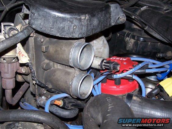
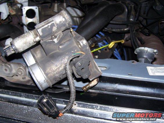
First you will need to locate the TPS and plug.
Plug
The TPS is located on the end of the throttle shaft on the throttle body (TB). By monitoring the output voltge from the TPS, the PCM can determine fuel delivery based on the throttle valve angle. A broken or loose TPS can casue intermittent bursts of fuel from the injector and/or an unstable idle. Any problems with the TPS will throw codes 23, 53 or 63 for the two digit system or 122 through 125 for the three digit code system.
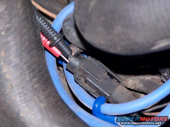
TO CHECK THE TPS: Turn the ignition to ON (engine not running) and install the probes of the volt-meter into the ground wire (black) and the signal wire (green) on the backside of the electrical connector. This process is called BACKPROBING. Turn your key to the on position (the engine need not be running to perform this test). Your meter should read 0.50-1.0 volts at idle. FYI...because the black probe kept on sliping out of the back of the plug I grounded it to the battery, which works just fine aso.
![Image]()
Rotate the throttle to the full-open position and the sensor should increase voltage to 4.0-5.0 volts. The maximum voltage I got was 1.85 volts. So I was for sure this must be the problem. Many have said that if you do not get a steady increase in voltage, this also is a sign of a bad TPS.
THROTTLE BODY REMOVAL: In most case you will need to remove the TB to get to the TPS. First remove intake hoses and the throttle cable assembly.
![Image]()
![Image]()
![Image]()
![Image]()
![Image]()
The bolts that hold the throttle assembly (located on top of the intake) are 1/2"
![Image]()
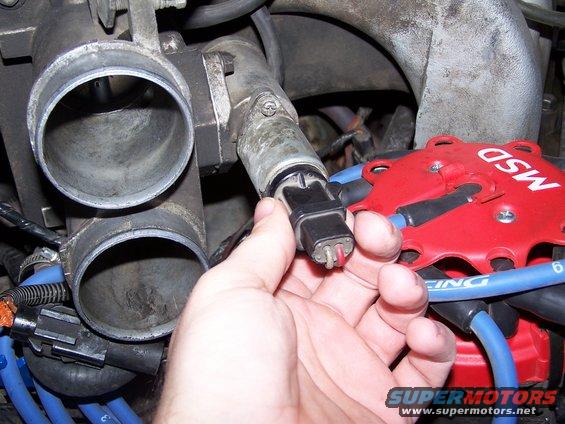
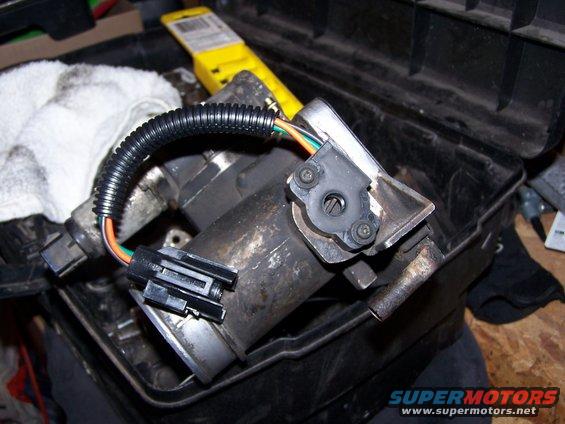
Next disconnect IAC plug, coolant hoses and vacuum lines. Remove the four bolts holding the TB to the intake. These bolts are 3/8".
This is the bottom of the TB where the TPS is located
![Image]()
While you have this apart...check the intake and TB for crud build-up
![Image]()
![Image]()
![Image]()
![Image]()
Mine was looking pretty nasty. Get some of this, a toothbrush and a rag and start cleaning it out:
![Image]()
CLEAN TB AND INTAKE:
![Image]()
![Image]()
Here is the new sensor to be installed...normal pracie was $54.99 my cost was $34.50, comes with a life-time warranty. While I was at it I decided to pick up a NEW Haynes manual. By the time it was all said and done I got the sensor and manual for original price of the sensor...christmas has come early!
INSTALL:
New sensor should be positioned the same as the old...wiring harness pointed away from the IAC. Engage the tanges of the sensor with the throttle shaft blade, then rotate it clockwise to align the reference marks before installing the screws.
![Image]()
Reinstall the TB in reverse order. Make sure you hook vac lines, coolant lines and sensor wires up.
See Throttle Position Sensor (TPS) Overview, Test & Adjustment by Seattle FSB @
So after reading many threads, I decided that the truck needed a tune-up. So I replaced cap and rotor with MSD, plugs, plug wires (Ford 9 mm) and even decided to go with a higher performing coil (Accel Supercoil). I also did the Seafoam thing (see my write up). It ran smoother but I would still get the hesitation/bucking.
BACK TO THE DRAWING BOARD: Started reading more threads on TPS, IAC and MAP. Decided to clean the IAC...someone on here had a great write up...search if your are interested. No change..smoother idle though!
Prior to removing the TPS, remove the negative battery cable. Some truck years will require that you scribe a mark across the sensor and the TB to ensure that the new sensor is installed in the same exact location. I was not sure about my truck so I did it anyway.

DIAGNOSIS: Decided it must be TPS...yeah I know...look for codes. This time I did not have too! See below if you even suspect you have a TPS issue. There is a voltage test you can perform to determine if the TPS is within normal oerating ranges.
First you will need to locate the TPS and plug.
Plug
The TPS is located on the end of the throttle shaft on the throttle body (TB). By monitoring the output voltge from the TPS, the PCM can determine fuel delivery based on the throttle valve angle. A broken or loose TPS can casue intermittent bursts of fuel from the injector and/or an unstable idle. Any problems with the TPS will throw codes 23, 53 or 63 for the two digit system or 122 through 125 for the three digit code system.
TO CHECK THE TPS: Turn the ignition to ON (engine not running) and install the probes of the volt-meter into the ground wire (black) and the signal wire (green) on the backside of the electrical connector. This process is called BACKPROBING. Turn your key to the on position (the engine need not be running to perform this test). Your meter should read 0.50-1.0 volts at idle. FYI...because the black probe kept on sliping out of the back of the plug I grounded it to the battery, which works just fine aso.
Rotate the throttle to the full-open position and the sensor should increase voltage to 4.0-5.0 volts. The maximum voltage I got was 1.85 volts. So I was for sure this must be the problem. Many have said that if you do not get a steady increase in voltage, this also is a sign of a bad TPS.
THROTTLE BODY REMOVAL: In most case you will need to remove the TB to get to the TPS. First remove intake hoses and the throttle cable assembly.
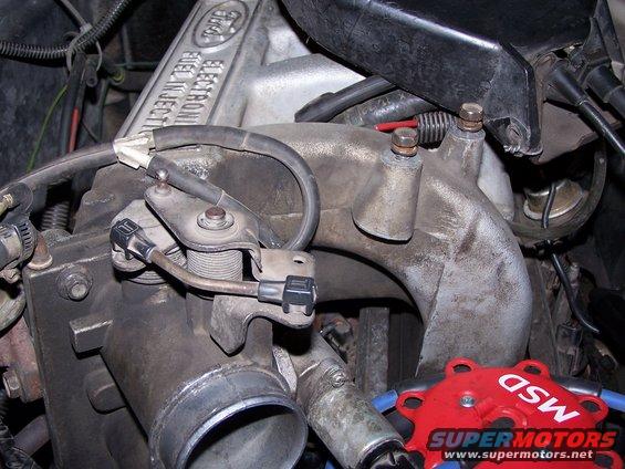

The bolts that hold the throttle assembly (located on top of the intake) are 1/2"

Next disconnect IAC plug, coolant hoses and vacuum lines. Remove the four bolts holding the TB to the intake. These bolts are 3/8".
This is the bottom of the TB where the TPS is located
While you have this apart...check the intake and TB for crud build-up


Mine was looking pretty nasty. Get some of this, a toothbrush and a rag and start cleaning it out:

CLEAN TB AND INTAKE:


Here is the new sensor to be installed...normal pracie was $54.99 my cost was $34.50, comes with a life-time warranty. While I was at it I decided to pick up a NEW Haynes manual. By the time it was all said and done I got the sensor and manual for original price of the sensor...christmas has come early!
INSTALL:
New sensor should be positioned the same as the old...wiring harness pointed away from the IAC. Engage the tanges of the sensor with the throttle shaft blade, then rotate it clockwise to align the reference marks before installing the screws.
Reinstall the TB in reverse order. Make sure you hook vac lines, coolant lines and sensor wires up.
See Throttle Position Sensor (TPS) Overview, Test & Adjustment by Seattle FSB @


